
Original Instructions


|
Appendix 1 - Essential health and safety requirements
|
||||
|---|---|---|---|---|
|
1.1.1
|
1.2.2
|
1.5.1
|
1.7.3
|
3.3.2
|
|
1.1.2
|
1.2.3
|
1.7.1
|
1.7.4
|
3.3.3
|
|
1.2.1
|
1.2.4.1
|
1.7.2
|
3.3.1
|
3.3.5
|

|
Harmonized standards (RED)
|
||
|---|---|---|
|
Article 3.1 a (Electrical safety):
|
EN ISO 60204-1:2018
|
|
|
Article 3.1 b (EMC):
|
EN ISO 13766-1:2018, EN ISO 13766-2:2018
|
|
|
Article 3.2 (Radio):
|
ETSI EN 300 328 v 2.2.2
|
|

|
Remarks
| ||
|
The stated safety information is independent of the base machine and directly concerns the engcon DC3.
|
|
Remarks
| ||
|
Other safety instructions can be found in the tiltrotator user manual.
|
 |
Danger
| |
|
Indicates that an accident will occur if the regulation is not
followed. Risk of personal injury or death.
|
|
|
Warning
| |
|
Indicates that an accident may occur if the regulation is not
followed. Risk of personal injury or death.
|
|
|
Caution
| |
|
Indicates that an accident may occur if the regulation is not
followed. Risk of personal injury.
|
|
Important
| ||
|
Indicates that an accident may occur if the regulation is not
followed. Risk of
damage to property, process or the surroundings.
|
|
Remarks
| ||
|
Specifies additional information that may make performance or understanding of specific operations easier.
|
 |
Track control
|
 |
Track control
|
 |
Wheel control
|
 |
Base machine
|
 |
Drive forward/reverse
|
 |
Rotation/slew right/left
|
 |
Tool change in the tool program
|
 |
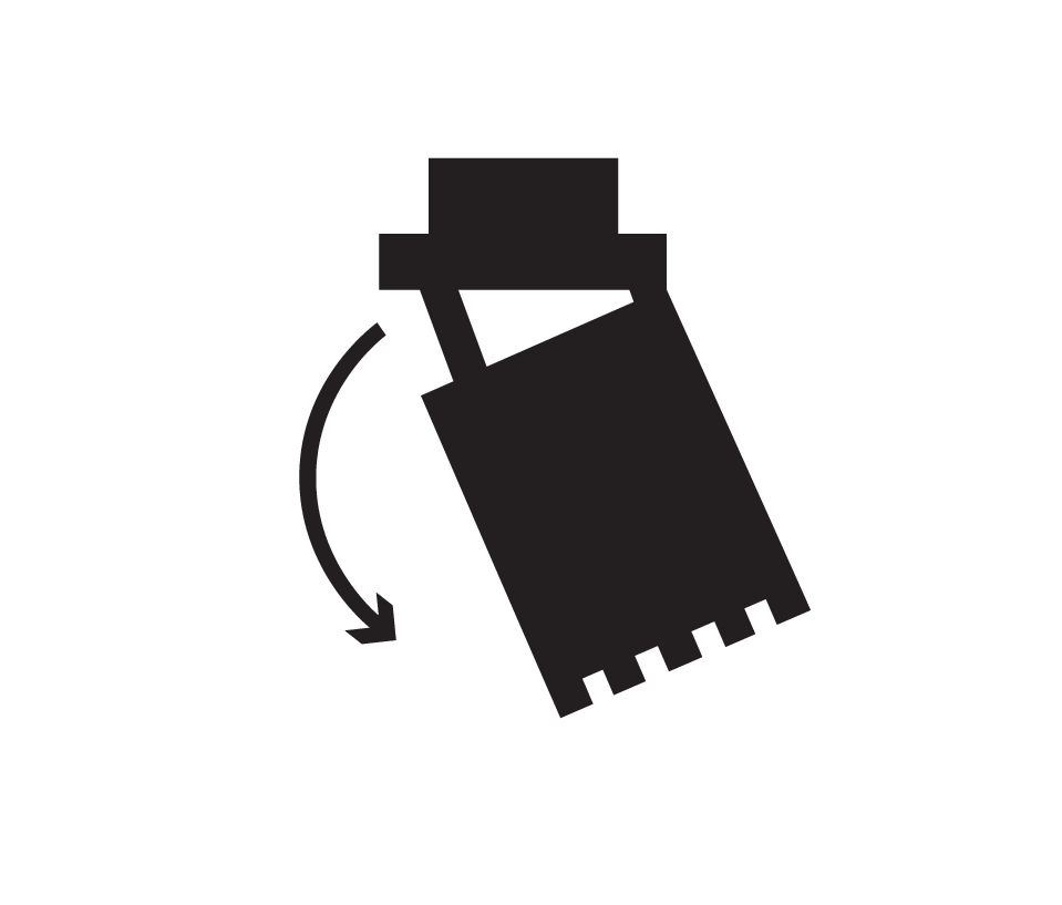
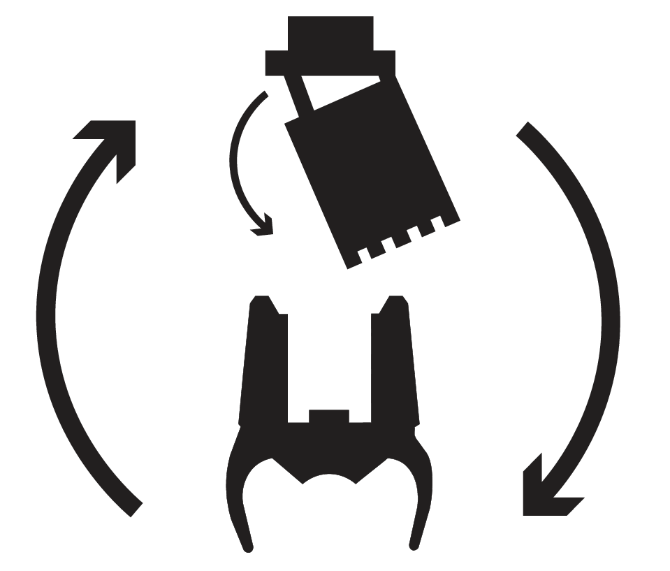
Feeder Swap
|
 |
Rotation
|
 |
Tilt
|
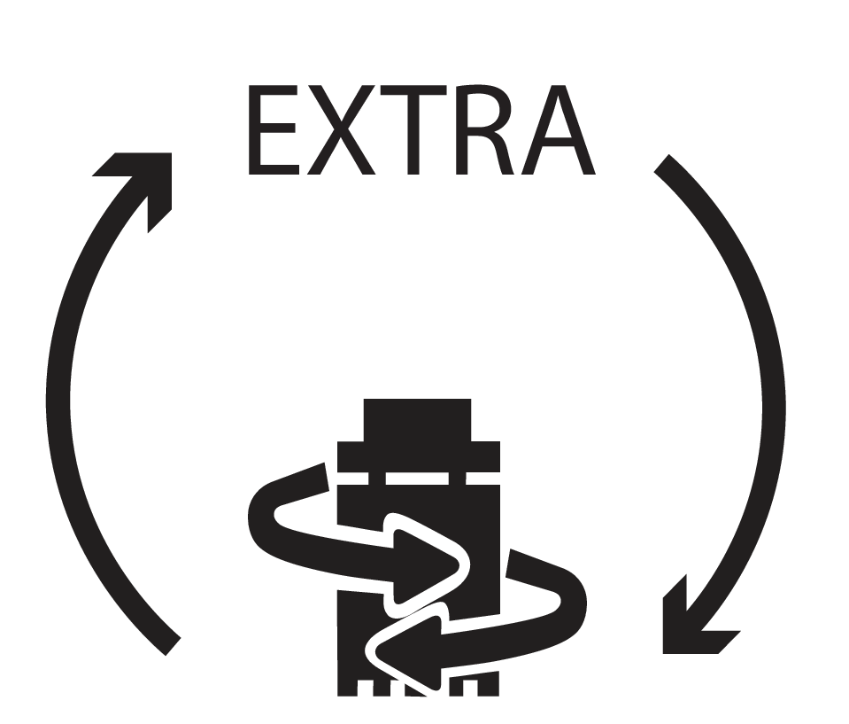 |
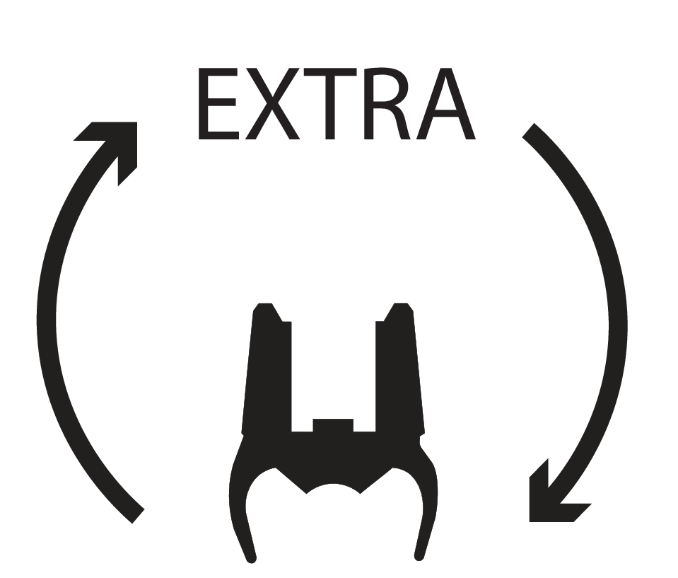
Shift between rotation and Extra 2
|
 |
Shift between tilt and Extra 2
|
 |
Open grab
|
 |
Close grab
|
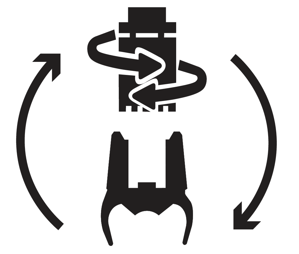 |
Shift between rotation and grab
|
 |
Shift between tilt function and grab
|
 |
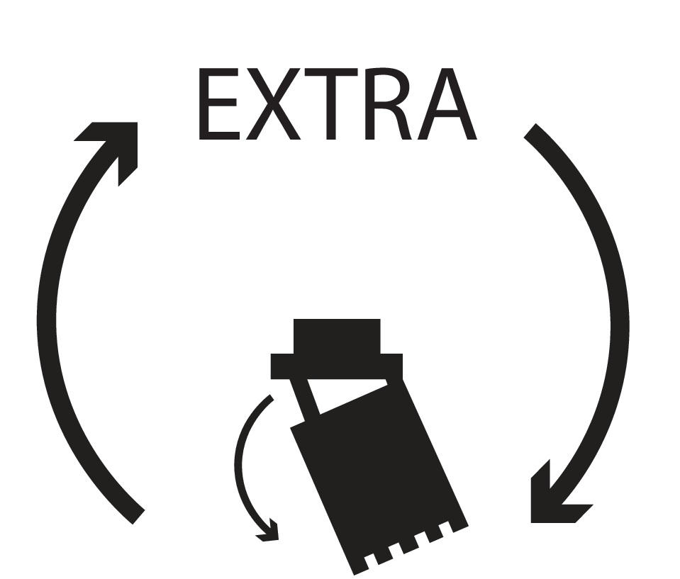
Shift between Extra and grab
|
 |
Joystick function
|
 |
Grapple
|
 |
Grapple rotation
|
 |
Open grab
|
 |
Close grab
|
 |
Clockwise grapple rotation
|
 |
Counterclockwise grapple rotation
|
 |
Grab
|
 |
Grab rotation
|
 |
Grab open
|
 |
Grab close
|
 |
Grab clockwise rotation
|
 |
Grab counterclockwise rotation
|
 |
Bucket in
|
 |
Bucket out
|
 |
Stick in
|
 |
Stick out
|
 |
Float position
|
 |
Float position
|
 |
Scissors open
|
 |
Scissors close
|
 |
Leveling blade up
|
 |
Leveling blade down
|
 |
Leveling blade up/down
|
 |
Support leg up/down
|
 |
Support leg up
|
 |
Support leg down
|
 |
Swing axle locked
|
 |
Swing axle off
|
 |
Boom
|
 |
Boom slew
|
 |
Boom slew left
|
 |
Boom slew right
|
 |
Side-shift
|
 |
Cruise control
|
 |
Auto idle
|
 |
Auto idle
|
 |
Auto idle
|
 |
Automatic gas
|
 |
Quick hitch lock
|
 |
Quick coupler lock valve
|
 |
Quick hitch lock (Front loader)
|
 |
Quick hitch lock (Excavator arm)
|
 |
12 Volt
|
 |
Forward gear
|
 |
24 Volt
|
 |
Neutral gear
|
 |
15 Amps
|
 |
Reverse gear
|
 |
EC Tiltrotator
|
 |
Driving direction
|
 |
Autotilt
|
 |
External circuit
|
 |
Open
|
 |
Locked
|
 |
Menu
|
 |
Communication radio
|
 |
Rotating brush
|
 |
Hammer
|
 |
Horn
|
 |
Parking brake
|
 |
Crawler gear
|
 |
Constant flow
|
 |
Low gear
|
 |
High gear
|
 |
Power boost
|
 |
Power boost
|
 |
Windscreen wipers
|
 |
Main beam/dipped beam
|
 |
User 2
|
 |
User 3
|
 |
Extra function 1
|
 |
Extra function 2
|
 |
Extra function Direction A
|
 |
Extra function Direction B
|
 |
Extra function Direction A
|
 |
Extra function Direction B
|
 |
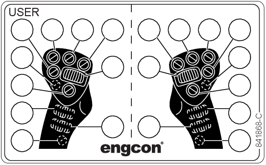
User function
|
 |
 |
Opening the quick coupler
|
 |
Closing the quick coupler
|
|
 |
Swing/height restriction
|
|
 |
Ground contact
|
|
 |
Alarm indicator
|
|
 |
Quick coupler for machine
|
|
 |
Quick coupler for tiltrotator
|
|
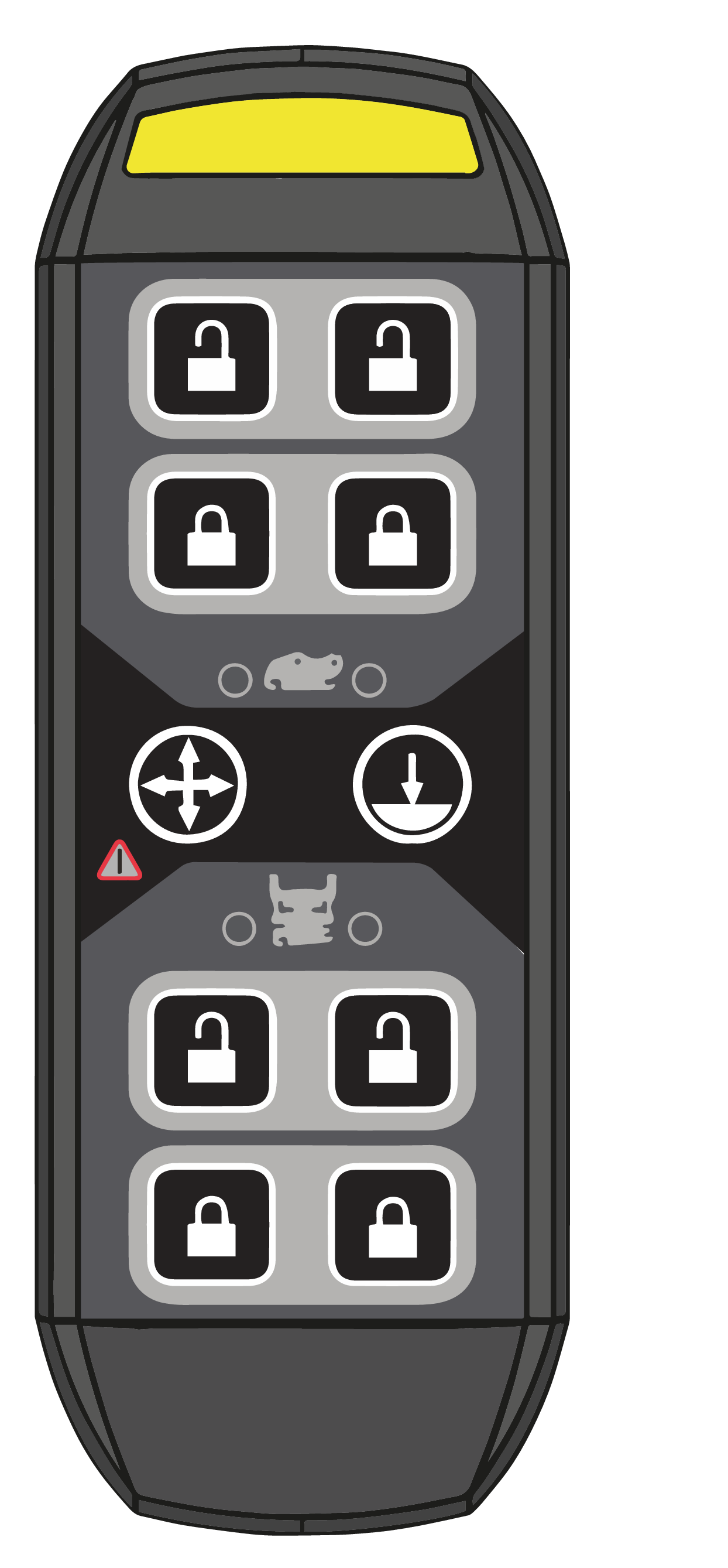
Symbol
|
Button press
|
Steady light indicates that
|
|---|---|---|
 |
Initiates lock opening sequence
|
Lock opening sequence can be initiated
|
 |
Ground contact is required
|
|
|
Or 1
|
Overrides ground contact
| |
|
Or 2
|
Shows ground contact sensor status
|
The sensor detects pressure
|
 |
Opens the lock
|
The lock can be opened
|
 |
Closes the lock
|
The lock can be closed
|
 |
Confirms machine blocking
|
Machine blocking is active
|
|
Or 1
|
Cancels machine blocking temporarily
|
-
|
|
Remarks
| ||
|
For quick couplers other than Q-Safe, follow the manufacturer's instructions for checking that tools are correctly connected.
|
 |
 |
|
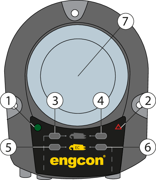
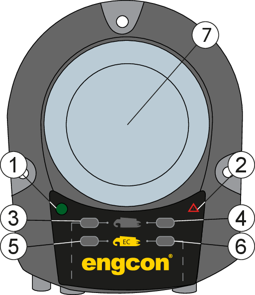
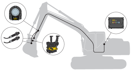
Position
|
Description
|
|---|---|
|
1
|
Power supply
|
|
2
|
Alarm indication
|
|
3
|
Sensor, machine coupler hook
|
|
4
|
Sensor, machine coupler ejector
|
|
5
|
Sensor, quick coupler hook
|
|
6
|
Sensor, quick coupler ejector
|
|
7
|
Warning lamp
|
|
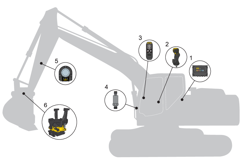
Position
|
Designation
|
|---|---|
|
1
|
Electronics module - MGM
|
|
2
|
Joystick - MIG2
|
|
3
|
Control panel - QPM
|
|
4
|
Ground pressure sensor
|
|
5
|
Electronics module - QLM
|
|
6
|
Tiltrotator
|
|
|
Warning
| |
|
Beware of moving parts. A lack of awareness may lead to crush injuries. Risk of personal injury.
|
|
|
Warning
| |
|
Never attempt to increase the maximum capacity of the equipment by modifications not approved by the supplier. Risk of personal injury and damage to property.
|
|
|
Warning
| |
|
Do not attempt to install, use or maintain your tiltrotator and its associated equipment before reading and understanding all information about the tiltrotator, its supplementary equipment and the base machine. Pay particular attention to the safety information.
|
|
|
Warning
| |
|
Only trained operators may make changes to control system functions. Risk of injury.
|
|
Important
| ||
|
Maintenance and repair of the electrical system may only be carried out by professionally qualified persons.
|
|
Important
| ||
|
If you have any doubts concerning the safety aspects of your knowledge, the equipment or work, contact a dealer or engcon AB.
|
 |
 |
|
|
Warning
| |
|
Functions may move differently than expected. Use the app to check which functions are available. Risk of injury.
|
|
|
Warning
| |
|
Stop work immediately and begin troubleshooting if the system warns of a faulty tool connection during operation. Risk of personal injury and damage to property.
|
|
Remarks
| ||
|
Machine hydraulics must be activated in order for the QSC opening and closing function to work.
|
|
Remarks
| ||
|
Follow the manufacturer's instructions for connecting and disconnecting tools if you do not use a Q-Safe quick coupler.
|
 |
See separate instructions for use for the tiltrotator and machine coupler. Also available on the website or by contacting engcon.
|
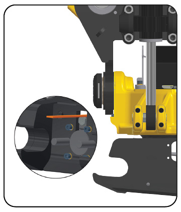 |
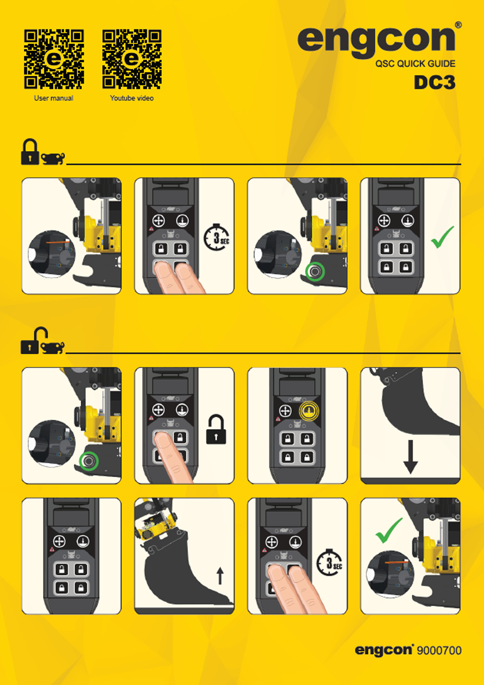
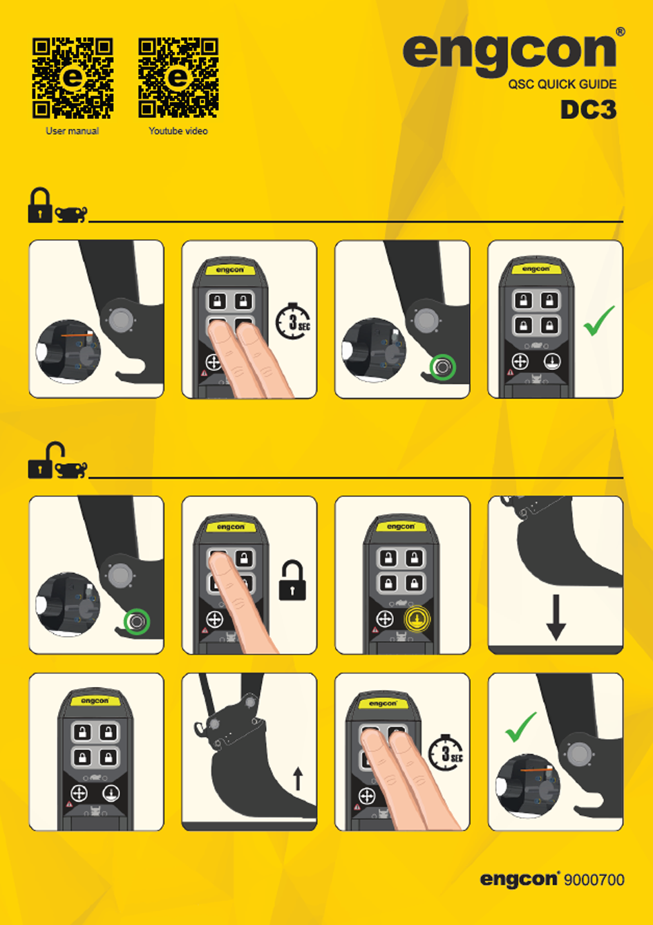
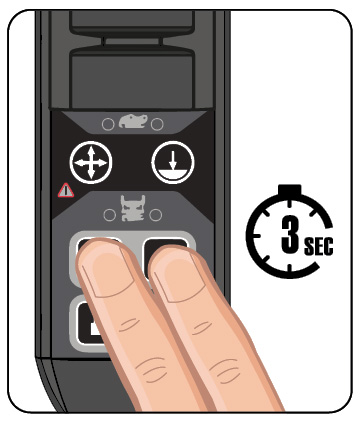
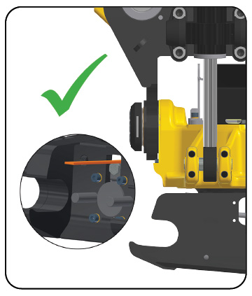
1. Check that the indicator rod is out.
|
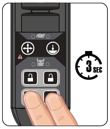 |
2. Hold down
  |
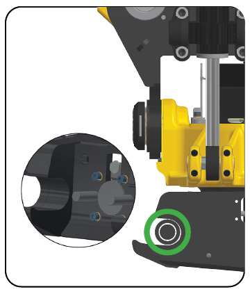 |
3. Check that the indicator rod is no longer visible and that the axle is in the correct position.
|
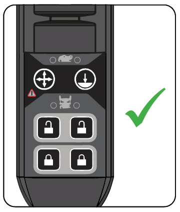 |
4. When the sound and light warning signals are deactivated, the tool is correctly connected.
|
|
|
Warning
| |
|
Make sure the product’s latches lock correctly according to the Instructions for use. Risk of personal injury or death.
|
 |
See separate instructions for use for the tiltrotator and machine coupler. Also available on the website or by contacting engcon.
|
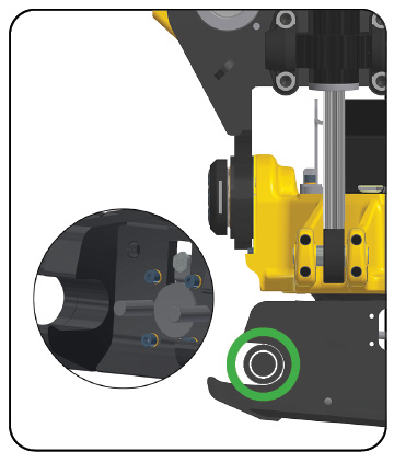 |
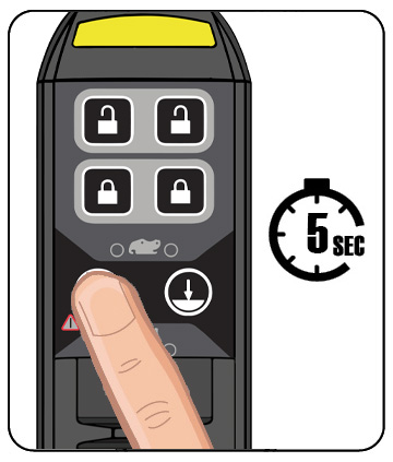
1. The indicator rod is not visible when the lock is closed.
|
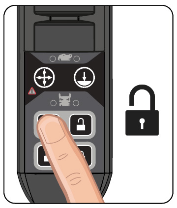 |
2. Press
 |
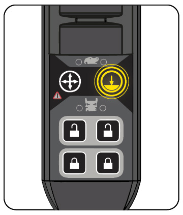 |
3. The icon
 |
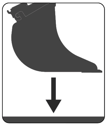 |
4. Lower the tool to achieve ground contact.
|
 |
5. The icon goes out when ground contact is achieved.
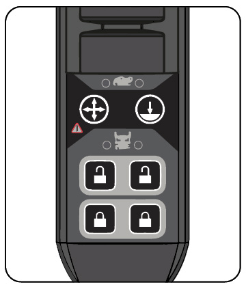
|
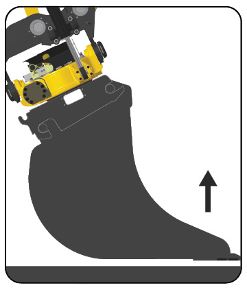 |
6. Raise the tool slightly above the ground to reduce the load during the locking operation.
|
 |
7. Hold down
  |
 |
8. Check that the indicator rod is out.
|
|
|
Warning
| |
|
Before starting up and calibrating the system make sure there is sufficient room to maneuver as there is a risk of the machine moving in a different way than expected. Risk of injury and damage to property.
|
|
|
Warning
| |
|
If you have any doubts concerning the safety aspects of your knowledge, the equipment or work, contact a dealer or engcon AB. Incorrect installation affect safety.
|
|
Important
| ||
|
Assembly and installation may only be carried out at a workshop authorized by the manufacturer. Changes to the assembly may not be carried out without the manufacturer’s consent.
|
|
Important
| ||
|
Maintenance and repair of the electrical system may only be carried out by professionally qualified persons.
|
 |
Hold down
 |
|
|
Warning
| |
|
In the case of alarms that cannot be remedied, contact an authorized service provider ASAP. The fault must be remedied before the machine may be used again. Risk of injury and damage to property.
|
|
|
Warning
| |
|
Stop work immediately and begin troubleshooting if the system warns of a faulty tool connection during operation. Risk of personal injury and damage to property.
|
|
|
Warning
| |
|
The hydraulic system must be de-pressurized before work on the system is begun. Risk of personal injury and damage to property.
|
|
|
Warning
| |
|
Never use your hands to search for leaks in the hydraulic system. Use the necessary protective equipment. Pressurized hydraulic oil can penetrate the skin. Risk of personal injury.
|
|
|
Warning
| |
|
Avoid contact with hydraulic oil. Risk of burns.
|
|
|
Warning
| |
|
Switch off power when working on the electrical system and remove any live objects before starting work Risk of personal injury.
|
|
|
Warning
| |
|
Beware of moving parts. A lack of awareness may lead to crush injuries. Risk of personal injury.
|
 |
 |
|
Position
|
Behavior
|
Indicates
|
Remarks
|
|---|---|---|---|
|
1
|
2 flashes
**_**_**_ |
Power supply OK
| |
|
2
|
1 flash
*_*_*_ |
CAN time out
| |
|
2 flashes
**_**_**_ |
Short circuit, power to sensor in EC
|
During start
|
|
|
3 flashes
***_***_***_ |
Short circuit, power to sensor in RF
|
During start
|
|
|
3 flashes
***_***_***_ |
Short circuit, power to sensor in EC
| ||
|
Inactive
|
No fault
| ||
|
3
|
Constant light
|
Connected tool
|
Hook sensor for machine quick coupler
|
|
4
|
Constant light
|
Connected tool
|
Ejector sensor for machine quick coupler
|
|
5
|
1 flash
*_*_*_ |
Tiltrotator removed
| |
|
Constant light
|
Connected tool
|
Hook sensor for the quick coupler under the tiltrotator
|
|
|
6
|
1 flash
*_*_*_ |
Tiltrotator removed
| |
|
Constant light
|
Connected tool
|
Ejector sensor for the quick coupler under the tiltrotator
|
|
|
7
|
Flashing white light and pulsating siren (normal behavior during coupling sequence)
|
Unsafe tool connection
|
Check attachment
|
|
Alarm
|
Description
|
Action
|
|---|---|---|
|
Alarm off
|
Correctly connected quick coupler or fully disconnected tool
| |
|
Flashing/beeping alarm
|
Possible faults:
Incorrectly connected RF or EC bracket Sensor fault Cable fault |
1. Check cables and connectors.
2. Check sensors for external damage. 3.Check LEDs 2-5 to continue troubleshooting. |
|
|
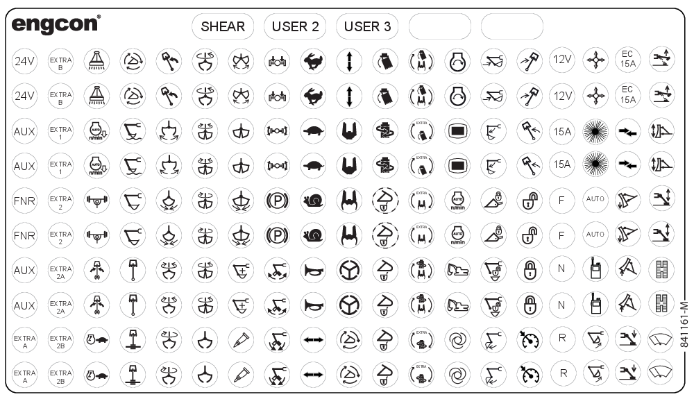
Warning
| |
|
Replace damaged or illegible signs and decals before using the machine. Risk of personal injury and damage to property.
|
|
|
Warning
| |
|
Before starting up and calibrating the system make sure there is sufficient room to maneuver as there is a risk of the machine moving in a different way than expected. Risk of injury and damage to property.
|
|
|
Warning
| |
|
Check that the function decals correspond to the machine functions before starting work. Risk of personal injury.
|
|
Term
|
Description
|
|---|---|
|
BCM
|
Base Control Module
|
|
C2C
|
CAN to CAN
|
|
DC3
|
Digging Control 3
|
|
EC
|
engcon (Engström Construction)
|
|
eML
|
engcon Machine Link
|
|
ePS
|
engcon Positioning System
|
|
eTT
|
engcon TechTool
|
|
MGM
|
Master Gateway Module
|
|
MIG2
|
Microprop Grip 2
|
|
QLM
|
Q-safe Light Module
|
|
QPM
|
Quick hitch Panel Module
|
|
QSC
|
Quick hitch Standard Control
|
|
TM3
|
Tiltrotator Module 3
|
 |
Delivery contents checked.
|
 |
Checked: hoses and cables are not at risk of pinching, cutting or stretch damage.
|
 |
Function check completed.
|
 |
Document check completed.
|
|
Machine model:
|
 |
|
Machine serial number:
|
 |
|
Tiltrotator serial number:
|
 |
|
Machine hitch serial number:
|
 |
|
Part number, machine electrical kit:
|
 |
|
Part number and version number of the installation instructions used for installation:
|
|
 |
|
 |
|
|
Machine owner, company:
|
 |
|
Date:
|
 |
|
Company installing equipment on the machine:
|
 |
|
Place:
|
 |
|
Date:
|
 |

|
engcon Australia Pty Ltd
+61 2 7252 5279 australia@engcon.com |
engcon Ireland Ltd
+353 15 686 742 ireland@engcon.com |
|
engcon Austria GmbH
+46 676 3786239 info-at@engcon.com |
engcon Korea Ltd
+82 70 4472 9978 engcon_kor@engcon.com |
|
engcon Belgium BVBA
+32 15 79 73 10 belgium@engcon.com |
engcon Netherlands
+31 85 82 23 550 netherlands@engcon.com |
|
engcon Canada Inc.
+1 438-226-1716 canada@engcon.com |
engcon North America Inc.
+1 203 691 5920 northamerica@engcon.com |
|
engcon Denmark A/S
+45 70 20 13 50 info@engcon.dk |
engcon Norway AS
+47 22 75 44 44 norge@engcon.com |
|
OY engcon Finland AB
+358 6322 815 finland@engcon.com |
engcon Poland Sp. z o.o.
+48 61 894 00 47 info@engcon.pl |
|
engcon France SAS
+33 1 60 79 49 70 france@engcon.com |
engcon Sweden AB
+46 670 65 04 00 sweden@engcon.com |
|
engcon Germany GmbH
+49 9342 934 85 0 germany@engcon.com |
engcon UK Ltd
+44 1684 297168 uk@engcon.com |
|
engcon International
+46 670 178 00 international@engcon.com |